A malfunctioning heating system often boils down to a small, box-shaped component that acts as the heart of your HVAC electrical system. A furnace transformer wiring diagram essentially maps the critical conversion point where your home’s high-voltage supply (120V) steps down to the safe low-voltage current (24V) required to operate your thermostat, gas valve, and control board. Without this correct wiring configuration, your furnace simply cannot receive the command to turn on.
Homeowners frequently encounter confusion when replacing these units due to varying wire colors and the distinction between primary and secondary sides. Understanding the diagram prevents costly damage to modern digital thermostats and sensitive circuit boards. This guide breaks down the complex schematic into actionable steps, ensuring you can safely diagnose and wire your furnace transformer.
Understanding the Basics of Furnace Transformers
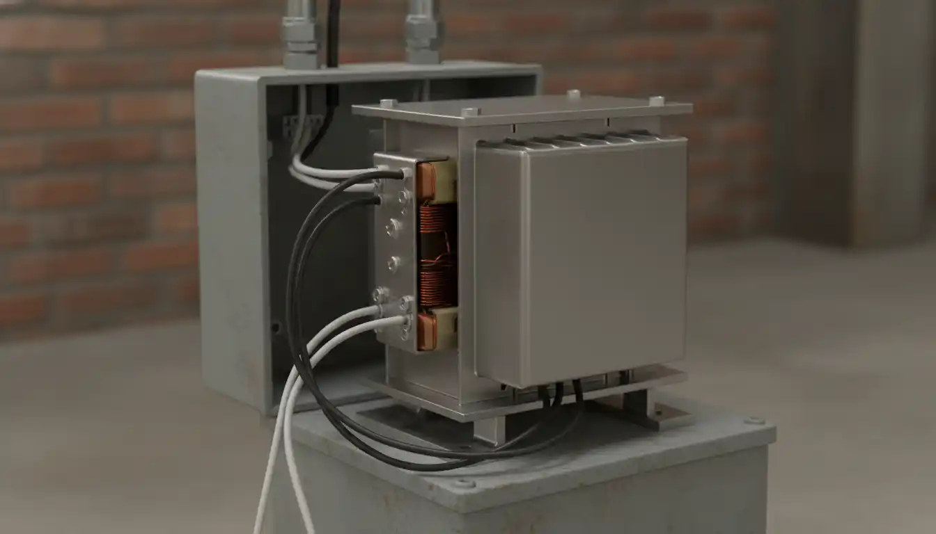
Before interpreting the wiring diagram, you must understand the function of the hardware. The transformer is a step-down device, meaning it takes the potentially lethal “line voltage” from your house mains and reduces it to a safer control voltage. This isolation protects the delicate electronics inside your thermostat and furnace controller.
Most residential furnaces utilize a standard 40VA (Volt-Ampere) transformer. The “primary” side handles the high voltage input, while the “secondary” side delivers the low voltage output. Identifying which wires belong to which side is the first step in successful wiring, as reversing these can lead to immediate equipment failure.
The Primary Side: Line Voltage
The primary side is where the power enters the transformer from your circuit breaker panel. in North America, this is typically 120 volts AC. On a standard universal transformer, you will usually find two wires on this side. The standard color code is Black for “Hot” (Line) and White for “Neutral.”
However, some multi-tap transformers include additional wires to accommodate different input voltages, such as 208V or 240V. These are often colored Red or Orange on the primary side. If your home uses standard residential power, you must cap these unused high-voltage wires separately to prevent short circuits.
The Secondary Side: Low Voltage
The secondary side outputs the 24 volts needed for the control circuit. This side is less dangerous to touch but highly sensitive to shorting against the metal chassis. The wires here are often thinner than the primary wires. Standard colors include Red (24V Hot) and often Blue or Brown (24V Common).
Modern furnaces rely heavily on the integrity of this secondary circuit. If you are renovating your utility room and managing moisture issues, perhaps considering waterproofing solutions like whether you can you paint over RedGuard near your equipment, ensure that no humidity compromises these exposed low-voltage terminals.
Detailed Breakdown of the Wiring Diagram
Reading the schematic requires distinguishing between the power source and the load. The diagram illustrates a flow of electricity that must be continuous for the furnace to fire. When you look at the schematic on the side of your new transformer or in your furnace manual, you will see two distinct coils represented by jagged lines.
Identifying Polarity and Phase
While alternating current (AC) technically switches direction, “polarity” in furnace wiring is crucial for safety and operation. The black wire must connect to the incoming switched power source. The white wire must connect to the neutral bundle. If these are swapped, the transformer will still produce 24V, but the furnace chassis remains energized relative to the internal components.
The Critical Role of the Common Wire
The “Common” wire (often labeled ‘C’ or ‘COM’) on the secondary side completes the 24V circuit. On older mechanical thermostats, this wire was unnecessary. However, modern smart thermostats require a constant flow of power to keep their screens lit and Wi-Fi radios active.
In a proper wiring diagram, one leg of the transformer’s secondary side connects directly to the ‘R’ terminal on the control board (Power). The other leg connects to the chassis ground and the ‘C’ terminal (Common). This grounding is vital for the flame rectification process, which we will discuss later.
Step-by-Step Replacement Instructions
Replacing a faulty transformer is a manageable DIY task if safety protocols are strictly followed. You will need a multimeter, wire strippers, and wire nuts. Always verify the specifications of your old unit before purchasing a replacement to ensure the VA rating matches.
1. Safety and Power Isolation
Locate the service switch on the side of the furnace or the designated breaker in your electrical panel. Turn the power off. Use a non-contact voltage tester to confirm that no current is flowing to the furnace. Working on live wires, even low voltage ones, risks blowing fuses on the main control board.
2. Disconnecting the Old Unit
Remove the access panel to the blower compartment. Take a clear photo of the existing wire connections for reference. Disconnect the wire nuts connecting the black and white primary wires. Then, disconnect the low voltage wires from the control board or the wire nuts connecting them to the thermostat bundle.
3. Wiring the New Primary Connections
Mount the new transformer securely. Connect the black wire from the furnace junction box to the black wire of the transformer. Connect the white neutral wire from the box to the white wire of the transformer. Ensure the connections are tight and no bare copper is visible outside the wire nut.
4. Wiring the Secondary Connections
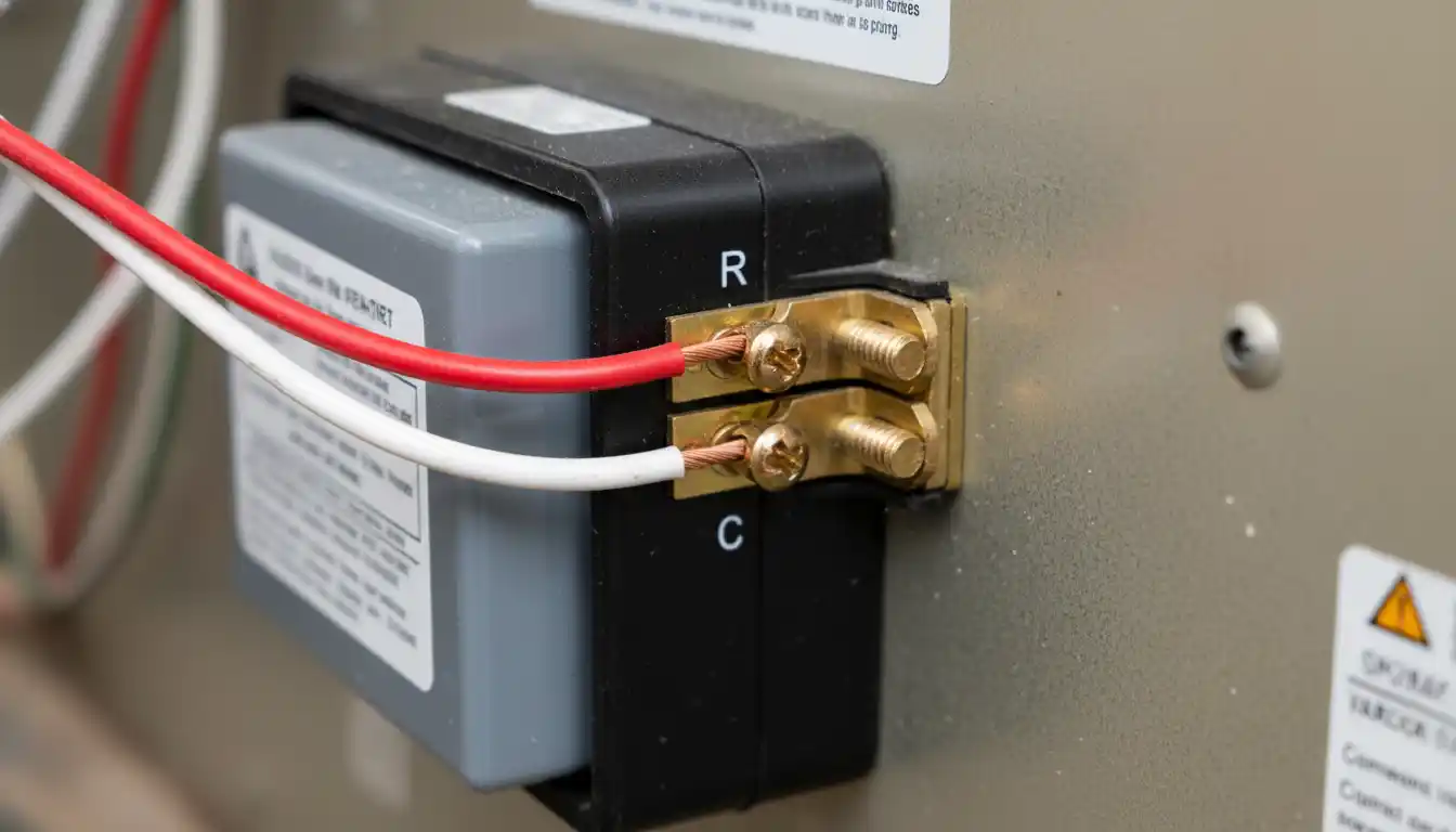
Connect the secondary leads to the control board. Typically, the Red wire goes to the ‘R’ or ’24V’ terminal, and the Blue/Brown wire goes to the ‘C’ or ‘COM’ terminal. If your transformer has screw terminals instead of wire leads, ensure you strip the wire cleanly and wrap it clockwise around the screw.
Advanced Troubleshooting: The Phasing Issue
One aspect of furnace transformer wiring that is rarely discussed but critically important is “phasing” and flame rectification. Modern high-efficiency furnaces use the flame itself as a conductor to prove that the fire is lit. This system, known as flame rectification, relies on a dedicated path from the flame sensor to the ground.
If your transformer wiring reverses the polarity on the primary side (swapping Line and Neutral), or if the secondary side is not properly referenced to the ground (floating secondary), the control board may fail to detect the flame. The furnace will fire up, run for a few seconds, and then shut down for safety.
When wiring a universal transformer, you must ensure that the side of the secondary coil intended to be “Common” is physically connected to the furnace chassis ground. Without this bond, the flame sensor cannot complete its micro-amp circuit, leading to confusing lockout codes that mimic a bad sensor.
Transformer Load and VA Ratings
Not all transformers are created equal. The “VA” rating determines how much power the transformer can supply. A standard 40VA transformer can handle the gas valve and a standard thermostat. However, adding humidifiers, zone valves, or power-hungry smart thermostats increases the load.
If you overload the transformer, the voltage will drop below 24V, causing contactor chatter or board resets. In severe cases, the internal thermal fuse will blow permanently. Just as you might check the weight of an empty 410a cylinder to ensure you have the right capacity for a recharge, you must calculate your electrical load capacity before adding accessories.
| Component | Typical Load (VA) | Notes |
|---|---|---|
| Gas Valve | 12 – 15 VA | The main solenoid draws significant power. |
| Control Board | 5 – 8 VA | Includes relays and logic circuits. |
| Smart Thermostat | 3 – 5 VA | Models with large screens draw more. |
| Contactor (A/C) | 10 – 15 VA | Energized only during cooling cycles. |
| Total Recommended | Max 40 VA | Do not exceed 80% of rated capacity for longevity. |
Diagnosing Failure Symptoms
If your new wiring is correct but the system fails to start, verify the output voltage. Set your multimeter to AC Volts and probe the secondary terminals. You should read between 24V and 28V. A reading of 0V indicates a blown internal fuse or a lack of primary power.
Sometimes, external factors affect electrical components. For example, water leaks dripping onto the furnace cabinet can short out the transformer. Checking the exterior of your home, such as ensuring portico gutters are directing water away from the foundation, is a proactive maintenance step that protects your indoor HVAC electronics.
A humming noise often indicates a transformer under heavy load or one with loose laminations. While a slight hum is normal, a loud buzz suggests the component is struggling or physically loose. Tightening the mounting screws or verifying the total VA load can often resolve this nuisance.
Final Testing and Verification
Once wired, turn the power back on. The furnace control board should light up with a solid status light or a slow “heartbeat” pulse. Adjust the thermostat to call for heat. Listen for the click of the relays and the ignition sequence.
If the fuse on the control board pops immediately, you likely have a “dead short” in the low voltage wiring. This often happens if the R and C wires touch or if a thermostat wire is pinched against the ductwork. Trace the wiring carefully to find the exposed copper causing the short.
By following this furnace transformer wiring diagram guide and paying attention to polarity and grounding, you ensure a reliable heating system. Correct wiring not only fixes the immediate problem but also safeguards your expensive HVAC components for years to come.