Encountering three black wires inside a light switch box can be a perplexing sight for any homeowner or DIY enthusiast. This common scenario often leads to confusion and apprehension, especially when you’re trying to replace a faulty switch or install a new one.
Understanding the function of each wire is not just about getting your light to work; it’s fundamentally about ensuring the safety and integrity of your home’s electrical system.
Demystifying the Three Black Wires: What Do They Mean?
The presence of three black wires typically indicates a more complex wiring configuration than a simple two-wire switch. Unlike the straightforward line-and-load setup, these additional wires serve specific purposes crucial to the circuit’s operation.
Incorrectly connecting these wires can lead to non-functional lights, tripped breakers, or even dangerous electrical hazards.
Common Scenarios for Three Black Wires
There are a few primary reasons why you might find three black wires in your light switch box. Each scenario demands a distinct approach to identification and connection.
Recognizing the underlying wiring pattern is the first critical step toward a successful and safe installation.
Scenario 1: Power Feed-Through (Most Common)
In many homes, especially older ones, the electrical power might “feed through” the light switch box to provide power to other outlets or switches further down the circuit. In this setup, you typically have:
- One Hot (Line) Wire: This wire brings continuous power from the circuit breaker to the switch box.
- One Switch Leg (Load) Wire: This wire carries power from the switch to the light fixture when the switch is in the “on” position.
- One Continuously Hot (Feed-Through) Wire: This third black wire is also connected to the incoming hot wire and carries power onward to another device or part of the circuit, regardless of the light switch’s position.
This configuration ensures that other devices on the same circuit receive power even when the light controlled by the switch is off.
Scenario 2: Three-Way Switch Configuration
If your light fixture is controlled by two different switches in separate locations (e.g., at the top and bottom of a staircase), you have a three-way switch system. In this setup, one of the three-way switches might have three black wires, typically representing:
- One Common Wire: This wire is the constant hot wire from the power source or the switch leg going to the light fixture.
- Two Traveler Wires: These wires carry power between the two three-way switches, alternating the path of electricity to control the light.
Three-way switches are designed to work in tandem, and their wiring is distinct from a single-pole switch with a feed-through.
Scenario 3: Switch Loop (Power at Fixture)
Less commonly, especially when dealing with strictly black wires, power might enter the light fixture box first, and then a “switch loop” runs down to the switch. In older wiring, both wires in this loop might be black, with one acting as the unswitched hot and the other as the switched hot returning to the fixture.
However, modern codes typically require a white wire in a switch loop to be re-identified as hot using black electrical tape or marker.
The Critical First Step: Ensuring Your Safety
Before touching any wires, prioritizing safety is paramount. Working with electricity carries inherent risks, and neglecting proper precautions can lead to serious injury or property damage.
Never assume a circuit is dead; always verify before proceeding with any electrical work.
Essential Safety Precautions
- Turn Off Power at the Breaker: Locate your home’s electrical service panel and identify the circuit breaker that controls the light switch you’re working on. Flip it to the “off” position. If unsure, turn off the main breaker to cut power to your entire home.
- Verify with a Non-Contact Voltage Tester: After turning off the breaker, use a non-contact voltage tester to confirm that no power is present in the wires. Touch the tester to each black wire individually. A lack of light or sound from the tester indicates the circuit is de-energized.
- Wear Personal Protective Equipment (PPE): Always wear insulated gloves and safety glasses when working with electrical wiring.
- Work in a Well-Lit Area: Good visibility helps prevent errors and ensures you can clearly see the wires and connections.
Taking these safety steps seriously minimizes risks and builds a foundation for a successful wiring project.
Tools You’ll Need for Identification and Wiring
Having the right tools makes the job safer, easier, and more accurate. Gather these items before you begin to avoid interruptions.
Each tool plays a specific role in safely identifying and connecting your light switch wires.
- Non-Contact Voltage Tester: For initial safety checks.
- Multimeter or Voltage Tester (with probes): Essential for accurately identifying live wires and verifying voltage.
- Screwdrivers (Phillips and Flathead): For removing switch plates and connecting wires to terminals.
- Wire Strippers/Cutters: For preparing wire ends for connection.
- Electrical Tape: For marking wires and providing additional insulation.
- Wire Nuts: For making secure and insulated connections between wires.
- Needle-Nose Pliers: Useful for shaping wire ends for terminal connections.
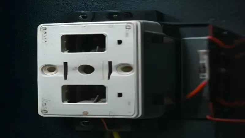
Step-by-Step Guide: Identifying and Wiring Your 3 Black Wires
This section provides a detailed, methodical approach to identifying each black wire in your light switch box. Following these steps carefully will ensure a correct and safe installation.
Patience and precision are key when working with electrical circuits.
Step 1: Prepare the Wires for Testing
Gently pull the switch and wires out of the electrical box. Carefully separate the three black wires so they are not touching each other or the box.
Ensure that no bare wire ends are exposed, or if they are, cap them with wire nuts temporarily for safety during testing.
Step 2: Re-Energize the Circuit (Temporarily for Testing)
Return to your service panel and flip the circuit breaker back to the “on” position. This is a critical step for identifying the live wire, but it must be done with extreme caution.
Do not touch any bare wire ends while the power is on.
Step 3: Identify the Constant Hot (Line) Wire
This is the most crucial step. Using your multimeter or voltage tester, carefully touch one probe to the bare copper ground wire (if present) or a grounded metal box, and the other probe to the bare end of each black wire, one at a time.
The wire that shows a reading of approximately 120 volts (or your local standard voltage) is the constant hot (line) wire. This wire is always live when the breaker is on, regardless of the switch position.
Immediately mark this wire with a piece of electrical tape of a different color (e.g., red or white) so you can easily identify it later. This prevents confusion during subsequent steps.
Step 4: Identify the Switch Leg (Load) Wire
Once the constant hot wire is identified and marked, turn the power off at the breaker again. Connect the identified constant hot wire to one of the screw terminals on your new light switch.
Now, take one of the remaining two black wires and connect it to the other screw terminal on the switch. Leave the third black wire disconnected and isolated.
Turn the power back on at the breaker. Flip the light switch to the “on” position. If the light fixture comes on, the wire connected to the second terminal is your switch leg (load) wire. Mark this wire with a different color of electrical tape (e.g., blue).
If the light does not come on, turn the power off, disconnect the wire, and try the other remaining black wire in its place. Repeat the test.
Step 5: Identify the Feed-Through Wire (If Applicable)
After identifying and marking both the constant hot and the switch leg wires, the remaining unmarked black wire is your feed-through wire. This wire carries continuous power to another device or part of the circuit.
It’s vital to ensure this wire is properly connected to maintain power to other parts of your electrical system.
Step 6: Wiring the Switch Correctly
Once all three black wires are positively identified and marked, turn off the power at the breaker one final time. Now you can make the permanent connections.
For a standard single-pole light switch with a feed-through:
- Connect the Constant Hot (Line) Wire: This wire (e.g., marked red) connects to one of the screw terminals on the light switch.
- Connect the Switch Leg (Load) Wire: This wire (e.g., marked blue) connects to the other screw terminal on the light switch.
- Connect the Feed-Through Wire: This wire must be connected to the constant hot wire using a pigtail. Take a short piece of new black wire (a pigtail), strip both ends. Connect one end of the pigtail to the same screw terminal on the switch where the constant hot wire is attached. Then, use a wire nut to connect the other end of the pigtail to the original constant hot wire AND the feed-through wire. This creates a secure junction that provides continuous power to the feed-through wire while also supplying power to the switch.
Ensure all wire nuts are twisted on tightly and connections are secure. A loose connection can generate heat and cause future problems, including the potential for a glowing switch.
For scenarios involving a three-way switch, the wiring will be different, utilizing traveler terminals and a common terminal. If you suspect a three-way setup and are unsure, consulting a professional electrician is highly recommended.
Understanding the Pigtail Connection: Why It’s Crucial
The “pigtail” method is not just a suggestion; it’s an electrical best practice, especially when multiple wires need to share a single terminal connection, as with the constant hot and feed-through wires.
Directly inserting multiple wires into a single screw terminal is often against code and can create an unsafe, unreliable connection. The pigtail ensures each wire has a dedicated, secure point of contact.
This technique distributes the electrical load more evenly and reduces the risk of overheating or arcing due to loose connections. It’s a simple but incredibly effective way to enhance the safety and longevity of your wiring.
Common Mistakes and Troubleshooting Tips
Even with careful planning, issues can arise. Knowing how to troubleshoot common problems can save time and frustration.
Always remember to turn off the power before attempting any troubleshooting inside the electrical box.
Mistake 1: Not Turning Off Power
Solution: Always start by switching off the circuit breaker and verifying with a voltage tester. No step is worth the risk of electrical shock.
Mistake 2: Incorrect Wire Identification
Solution: Retrace your steps. Re-perform the wire identification process with the power on (briefly and cautiously) and your multimeter. Mark wires clearly with different colored electrical tape as you identify them.
Mistake 3: Loose Connections
Solution: After wiring, gently tug on each wire connected to the switch and inside the wire nuts. Any wire that comes loose indicates a poor connection that needs to be redone. Backstab connections are notorious for becoming loose over time; always opt for screw terminals or proper wire nuts.
Mistake 4: Light Not Working After Wiring
Solution:
- Check the Bulb: A simple oversight, but ensure the bulb is working and screwed in tightly.
- Check the Breaker: Confirm the breaker is still in the “on” position and hasn’t tripped.
- Re-Verify Wiring: Turn off power and carefully re-examine your connections against the identified wire types. Ensure the constant hot is on one terminal (or pigtailed to the switch and feed-through) and the switch leg is on the other.
- Test the Switch Itself: A rare but possible scenario is a faulty new switch.
When to Call a Professional Electrician
While many wiring tasks are manageable for a DIYer, there are situations where calling a licensed electrician is the safest and smartest course of action. Recognizing your limits is a sign of true expertise.
Complex or older wiring systems often require specialized knowledge and tools.
Signs You Might Need Professional Help:
- Uncertainty at Any Stage: If you’re ever unsure about wire identification, connection, or safety, stop and call an expert.
- Old or Damaged Wiring: Frayed wires, crumbling insulation, or aluminum wiring (common in homes built between 1965 and 1973) should be handled by professionals. Aluminum wiring requires specific connectors and techniques.
- Complex Systems: If you’re dealing with multiple switches in one box, unfamiliar conduit systems, or wiring that doesn’t match standard diagrams, an electrician can diagnose the situation accurately.
- Repeated Breaker Trips: If your breaker continues to trip after your wiring attempts, it indicates a short circuit or overload that needs professional attention.
- No Ground Wire: If your electrical box lacks a ground wire, an electrician can advise on proper grounding solutions, which are crucial for safety.
Investing in professional help ensures your home’s electrical system is safe, up to code, and functions correctly. It provides peace of mind that DIY attempts cannot always guarantee.
Understanding Your Home’s Electrical Flow for Better DIY
Beyond simply identifying wires, truly understanding the flow of electricity within your home’s circuits empowers you to tackle more complex projects confidently. Every wire has a story, a path it takes from the breaker panel to the device it powers.
Thinking about electricity not just as static connections but as a dynamic flow helps demystify many wiring challenges.
When you encounter three black wires, visualize the journey of power. One wire is the constant supplier, like a main road. Another is a branch road that powers the light, controlled by the switch as a gate. The third black wire is often a continuation of that main road, ensuring other towns (devices) further down still receive power.
This mental model helps you deduce which wire is which, even in unusual configurations. It moves beyond rote memorization of wiring diagrams to a deeper comprehension of electrical principles.
Common Black Wire Scenarios in Light Switch Boxes
| Scenario | Wire 1 (Black) | Wire 2 (Black) | Wire 3 (Black) | Typical Function |
|---|---|---|---|---|
| Single-Pole with Feed-Through | Constant Hot (Line) | Switch Leg (Load to Light) | Continuously Hot (to another device) | Controls one light, powers another device. |
| Three-Way Switch (One Switch Box) | Common (from Line or to Load) | Traveler 1 (to other 3-way switch) | Traveler 2 (to other 3-way switch) | Controls one light from two locations. |
| Switch Loop (Power at Fixture, older wiring) | Unswitched Hot (from fixture) | Switched Hot (back to fixture) | N/A (often only two black wires) | Power enters fixture, loops to switch, returns to fixture. (Less common to see *three* distinct black wires in this specific context without re-identification.) |
Final Checks and Restoration
After all connections are made and secured, it’s time for the final steps before closing up the electrical box.
These checks ensure everything is safe and functional.
- Insulate Exposed Wires: Ensure all bare wire ends are covered by wire nuts or electrical tape. No copper should be visible outside of terminal connections.
- Neatly Fold Wires: Gently push the wires and the new switch back into the electrical box, taking care not to pinch any wires or create strain on the connections.
- Install Switch Plate: Secure the switch to the electrical box and then attach the decorative switch plate.
- Restore Power and Test: Go back to your service panel, flip the circuit breaker to the “on” position, and test your new light switch. It should operate smoothly and consistently.
Successfully wiring a light switch with three black wires is a rewarding DIY accomplishment. By understanding the purpose of each wire and following a methodical, safety-first approach, you can confidently tackle this common home electrical task.
Always prioritize safety, take your time, and don’t hesitate to seek professional help if you encounter anything beyond your comfort level.